In this section, we are going to look at the fundamental aspects of modelling in 3D. If you have done any work in 3D, a lot of this will be old hat for you and you can safely skip ahead to the bottom for the Blender specific details.
3D Fundamentals
At the very core, 3D models are ultimately built up of 3 basic building blocks:
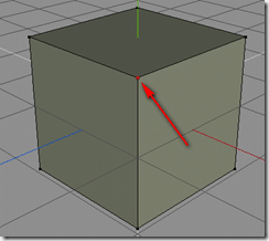
The Vertex
Vertex, or vertices ( plural ) are the very basic building blocks. In a nutshell, a vertex is a position in 3D space.
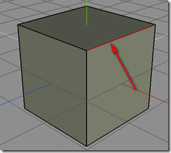
The Edge
An edge is simply the connection between two vertices.
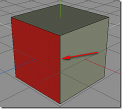
The Face
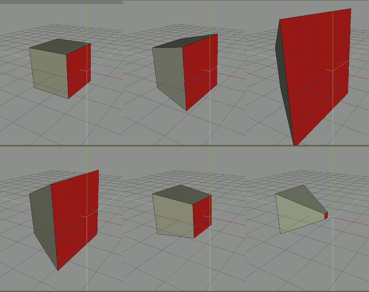
The Face ( or Polygon ) is the solid hull you get when you have 3 or more vertices connected by edges and forming a closed surface. Most rendering stacks, like OpenGL or DirectX are optimized to work with triangles. When modelling however, it is often easier and preferable to work with quads. Given that any quad can be turned into a triangle by splitting it corner to corner, it is incredibly easy to tessellate from a quad to a tri, so when you can, work with quads. It is possible to have more than 4 sided faces, we will cover this later in the form of BMesh, but behind the scenes they are simply performing the task for you. The problem with having shapes with more than 4 sides is you can no longer guarantee that they are flat, which can lead to some bizarre rendering artefacts.
There is one last concept that is important to understand…
The Normal
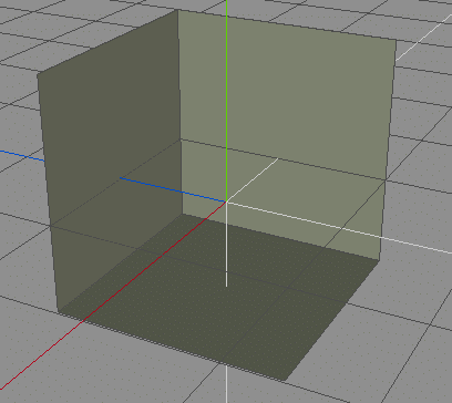
See the green lines?
Those are each faces “normals”. Basically the normal is the direction a face, um… faces. Most of the time you won’t have to deal with normals all that often, but if your face is “missing”, there is a good chance it’s normal has flipped.
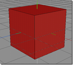
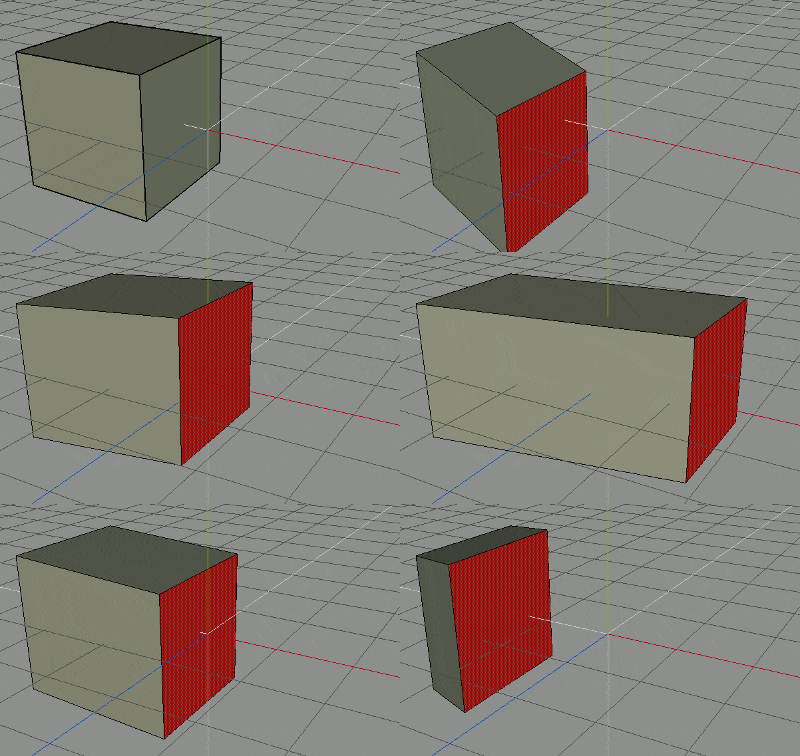
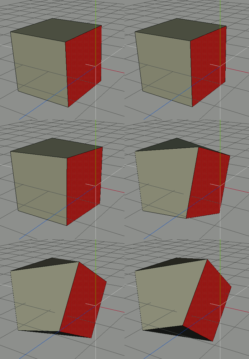
Take the above cube image, right now all the normals face outwards from the cube. Here is the same cube rotating, with it’s normals flipped:
Sometimes this is actually the behaviour you want, such as if you are modelling the interior of a space, like inside a room, or creating a skybox around the world.
Modelling in Blender
Configuring the 3D view
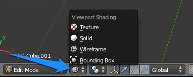
When working in 3D, you have a number of options for how you want your mesh displayed, you can work on a wireframe, solid or textured image. At the bottom of the 3D view screen, locate the sphere icon to bring up the Viewport Shading menu:
Which mode you ultimately select is up to you. I generally flip back and forth between all of them.
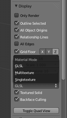
There is one other setting to be aware of, and this will determine how your scene will be displayed within Blender. If you want to match your game results as closely as possible, you probably want to set it to GLSL, which is OpenGL rendering. This is done from the properties window.
If the properties window isn’t currently being displayed, press N to display it. Scroll down to the section labeled Display, open the Material Mode drop down and select GLSL. If things aren’t displaying correctly for you, play around with the settings in this panel. Oh, and notice the Toggle Quad View button? If you like the 4 panel mode in 3D Studios Max, click this button to emulate it. I personally do not like the results, it’s better to simply configure display windows as you need them.
Ok, now that we have the screen rendering set up, lets actually start modelling.
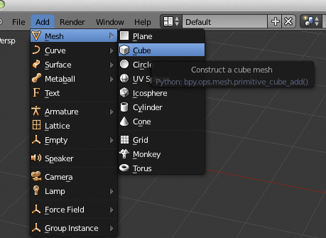
If you have a cube on screen already from the default scene, great. Otherwise we need to create one.
From the Menu, select Add->Mesh->Cube
A cube will then be created at the location of the cursor/pivot. It is actually incredibly common to start modelling with a simple cube, it’s called “box modelling” and we will look at in depth shortly.
Now that we have a 3D object to work with, there is a very important concept we need to address, object mode vs editing mode.
Object Mode vs Editing Mode
When working in Blender, you can be in a number of different modes, which completely changes the tools available and the way things perform. There are a number of different modes you can be in, but two are of importance to us right now, Object Mode and Edit Mode.
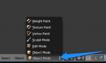
You can toggle between modes using the menu at the bottom of the 3D view:
You can also perform the same action by hitting the TAB key. Each time you hit the tab key, it toggles between modes. This is one of those things you will do A LOT, so it really helps to memorize that hotkey.
So, what then are the different modes? Well, Object mode is when you are dealing with a mesh or other scene objects ( lights, cameras, etc ) as a single entity. If you move something in Object mode for example, it moves the entire object. Edit mode on the other hand, works with the components of the mesh, those being the vertices, edges and faces. When you are actually changing the mesh, you will be working in EDIT Mode. As you may notice, when switching between modes, the tools and menu options available change massively.
Welcome to Edit Mode
During the modelling phase, you will spend a LOT of time here, so get used to it.
As I mentioned earlier, models are built of three basic building blocks, the vertex, edge and face. In edit mode, you have to choose which of those three levels you want to work at.
This once again can be accomplished using the menu at the bottom of the view menu. When in Edit Mode, you will see a series of buttons for switching between Vertex, Edge and Face editing mode. These buttons will only be available in Edit Mode. One option will always be selected, in this case Face mode.
These different modes once again change the tools available. More importantly, they change the way selections work… in Face mode for example, right clicking within the object will select the clicked Face. This effects all the various different selection tools too, such as the Border Select, Circle select, etc. It’s fairly common to switch between different modes regularly.
Fortunately there is yet another hotkey available, but this one requires a bit of dexterity to pull off.
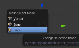
First off, pressing CTRL + TAB brings up the mode selection pop-up window, like so:
That said, for those with long enough fingers, there is yet another combinations of shortcuts to make things even faster
CTRL + TAB + 1 Select Vertex Mode
CTRL + TAB + 2 Select Edge Mode
CTRL + TAB + 3 Select Face Mode
Trust me, you will switch between modes A LOT. It is certainly worth your while to learn these hotkeys. I will admit, a 3 key hotkey is more than a bit annoying. One of the very first things I tend to do is define my own hotkey for each of these settings. There are perils in setting your own hotkeys ( you can clobber existing commands, plus documentation will no longer apply ). If you are interested in re-configuring Blender, you can read more about it here. I leave that decision to you; in many ways it makes sense to learn the Blender way first, then customize things to fit your needs later on.
Axis and Allies… no wait, just Axis!
There is one more important concept to cover before we carry on, the Axis, they play a very important role in 3D applications.
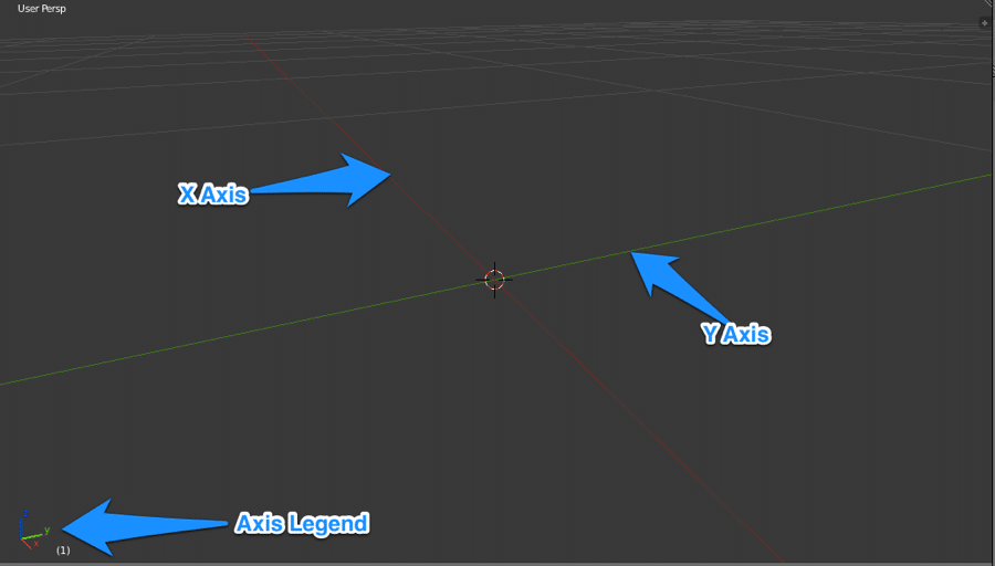
Let’s take a look at an empty Blender 3D scene:
Not shown in that example are the Z axis ( normally in blue ), which runs straight up and down.
Blender orientation is known as Z-up. In that up and down in the scene are along the Z axis. This corresponds with the camera, where looking down the Z-axis for example is the same as the “Top” camera, while looking up the Z-axis is the same as the “Bottom” camera. It is important to remember that different game engines use different orientation systems, as do different 3D programs. Some are Y-up, in which the Y axis denotes up and down. Fortunately switching between the two is a simple rotation away. You can read a bit more about the subject here if you are interested. It really only becomes important when you are moving between programs or exporting to a game engine.
Axis are important to understand because you commonly want to constrain your movements in a single direction only. We will cover this shortly.
Moving, Scaling and Rotating Things
There are 3 basic actions you will commonly want to perform on objects, or their vertices/faces/edges and those are moving( or translating), scaling and rotating. Let’s take a quick look at each. All of the operations we are about to describe work in either Object or Edit mode.
Move/Translation
Moving or translating is simple the act of well, moving something. In Blender though, it has a remarkably weird name/hotkey.
G , G as in Grab. Press G then move the mouse around to position your object. Then press the left button to finishing moving. Otherwise, press the right mouse button to cancel the move.
Remember earlier when I said you could constrain along a single Axis? Well, doing so is quite easy. After you press G to perform a move, press the axis you want to move along.
Move Along X Axis only: G then X then move mouse, then Left Mouse Button when done.
Move Along Y Axis only: G then Y then move mouse, then Left Mouse Button when done.
Move Along Z Axis only: G then Z then move mouse, then Left Mouse Button when done.
You can also move using just the keyboard. To do this, simply press G then the Axis letter to move along, then the amount, followed by Enter to commit, or Esc to cancel.
For example, to move 5 units along the Y axis, you would: Press G then Y then 5 followed by Enter. This is handy when you are going for precision movements or are modelling to scale.
That might seem like a lot to learn, but don’t worry, you only need to learn it once and it works basically identical for Scaling and Rotating.
Using The Widget
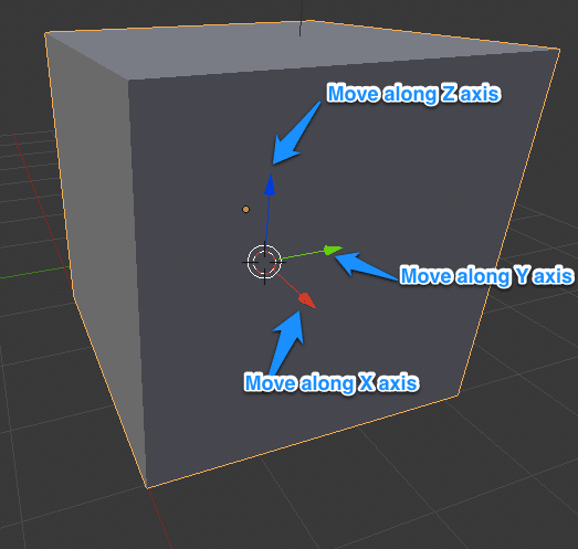
You may also notice that when you press G to move an object, a widget appears on screen. You can left click on an axis arrow to begin dragging in that direction:
Simply pick the axis you want to move along and hold down the Left Mouse Button. Once you have positioned where you want, release the Left Mouse Button, to cancel, click the Right Mouse Button.
Scaling
Scaling is the act of growing or shrinking an object or parts of it.
To Scale in Blender Simply hold the S key, Left Mouse Button Down, then move the mouse toward the pivot to shrink the object, or away in any direction to increase the size, release the button when complete. Click Right Mouse Button to cancel.
Like moving, you can constrain the scaling axis by holding X, Y or Z after you hit S.
Rotating
Rotating is simply the act of turning the object or parts of it.
To rotate an object in Blender simply hold the R key, then click and hold the Left Mouse Button, drag the mouse up or down and release when fully rotated. Once again Right Mouse Button cancels the rotation.
Right the other two operations, you can constrain rotation along a given axis by holding X,Y or Z after you press R.
Manual Entry
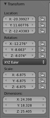
For all of these operations, you can directly enter numeric values if you prefer, or you can lock rotation around a given axis. If the Properties Window isn’t displayed, press N to display it.
Note however, that most of these options are only available when in Object mode. In Edit mode, you will have different selections. But if you want very precise positioning, or want to prevent movement along a certain axis, this is where you do it. Simply click and drag a value left or right to change it, or double click a value to enter a new one. Clicking the padlock will prevent movement of the given type on the given axis. For example, clicking the Padlock on the Z value of Location, while prevent your object from being able to move up or down on the screen.
Hotkeys / Actions used in the Tutorial
| Key/Action | Action |
|---|---|
| N | Show or Hide property window |
| G + LMB + Drag | Grab/Move/Translate selected item(s) |
| S + LMB + Drag | Scale selected item(s) |
| R + LMB + Drag | Rotate selected item(s) |
| S or G or R
+ X or Y or Z |
Limit scale,move or rotation to selected axis |
| S or G or R
+ X or Y or Z + Number value + ENTER |
Scale, move or rotate selected item(s) along selected axis by entered amount. Can use a decimal point. |
| TAB | Toggle current mode ( Object, Edit, etc ) |
| CTRL + TAB | Toggle between mesh select modes (Vertices, edges, faces ) |
| CTRL + TAB + 1 | Vertex editing mode ( must be in Edit mode ) |
| CTRL + TAB + 2 | Edge editing mode ( must be in Edit mode ) |
| CTRL + TAB + 3 | Face editing mode ( must be in Edit mode ) |
On to next part

